 İçeriğe atla
High-performance PTFE CNC machining for precision machined parts remains one of the most deceptively complex challenges in custom plastic fabrication.
PTFE (Polytetrafluoroethylene), widely known by the brand name Teflon®, is celebrated across semiconductor, chemical processing, medical, and aerospace industries for its exceptional chemical inertness, ultra-low coefficient of friction ($<0.05$), high thermal stability, and superior dielectric strength. Fakat, the very properties that make PTFE invaluable in demanding operating environments make it a nightmare to cut accurately on standard CNC equipment.
Unlike rigid engineering thermoplastics such as PEEK or Delrin (POM), virgin PTFE exhibits high softness, extreme ductility, low thermal conductivity, and a high coefficient of thermal expansion (CTE). Machining it without causing material creep, elastic spring-back, dimensional drift, or persistent heavy burrs requires specialized tooling geometries, tailored fixturing, and stringent thermal management.
For procurement managers and hardware design engineers sourcing critical seals, valve seats, electrical insulators, or fluid manifolds, understanding how a manufacturing partner navigates these material-specific nuances is the key to preventing costly assembly failures.
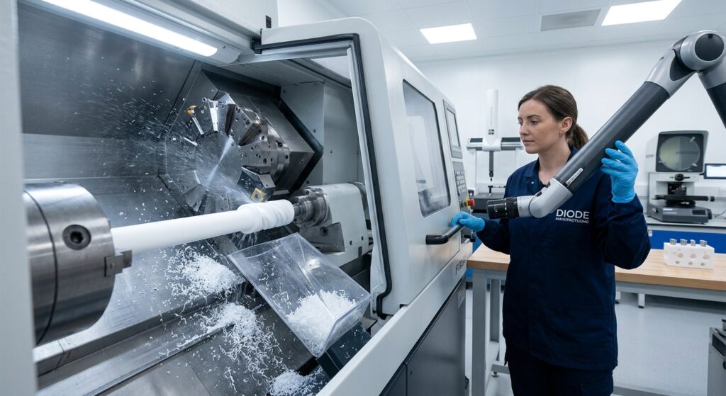
The Engineering Realities: Why PTFE CNC Machining is Inherently Difficult
To achieve micro-inch surface finishes and maintain tight tolerances ($pm 0.012text{ mm}$) on PTFE components, machinist teams must overcome four fundamental material behaviors:
1. High Elasticity and Elastic Spring-Back
PTFE possesses a low elastic modulus and high elongation rate. Under the cutting force of a conventional end mill or turning insert, the polymer pushes away and deforms under the blade rather than shear cleanly. Once the tool passes, the compressed material “springs back,” resulting in undersized bores, oversized shafts, and unexpected wall thickness variations.
2. High Thermal Expansion and Low Thermal Conductivity
PTFE expands rapidly when heated, with a CTE roughly 10 ile 12 times greater than that of 6061 alüminyum. Because its thermal conductivity is extremely low, frictional heat generated during cutting cannot dissipate into the chip or workpiece quickly. Yerine, heat accumulates right at the tool-material interface, causing local volumetric expansion during machining. When the finished part cools down to room ambient temperature ($20^circtext{C}$), it shrinks, rendering initially “accurate” measurements out-of-spec.
3. Material Creep and “Cold Flow” Under Clamping Pressure
PTFE is subject to cold flow—spontaneous deformation under constant mechanical stress at room temperature. Standard vise jaws, three-jaw chucks, or tight mechanical clamps easily crush or permanently distort thin-walled PTFE tubes and valve bodies before a single toolpath is executed.
4. Burrs and Thread Flashing
Due to its ductile nature, PTFE tends to push and stretch into long, stringy burrs along cut edges, tapped threads, and cross-drilled holes. Deburring soft fluoropolymers manually often scratches pristine sealing surfaces or alters critical lip geometries.
Best Engineering Practices for Precision PTFE Machining
At Diode Machining, overcoming PTFE’s material characteristics demands an integrated process approach spanning raw material conditioning, specialized tooling, and custom workholding strategies.
Advanced Tooling Geometries: Ultra-Sharp, High-Rake Cutting Edges
Standard carbide tools designed for aluminum or steel feature edge hone radii that push soft PTFE instead of slicing it. Precision PTFE cutting requires:
- Polished PCD (Polycrystalline Diamond) or Uncoated Carbide Inserts: Super-mirror polished flutes prevent plastic chips from galling or welding to the tool face.
- Extremely Sharp Cutting Edges: Zero or near-zero edge radius with high positive rake angles ($15^circ text{ ile } 25^circ$) and large clearance angles to minimize cutting force and reduce material push-down.
- Single-Flute End Mills for Milling: High-helix, single-flute cutters maximize chip clearance, carrying heat away from the cutting zone instantly.
Customized Workholding: Preventing Clamping Distortion
To hold soft PTFE without crushing it, conventional vise setups must be replaced with uniform-pressure fixtures:
- Custom Pie Collets and Soft Jaws: Contoured 360-degree contact jaws distribute clamping force evenly around cylindrical components.
- Vacuum Fixturing for Flat Stock: Holding thin PTFE plates using vacuum tables eliminates mechanical clamping stress completely, keeping parts flat during high-speed pocketing.
- Internal Mandrels and Support Sleeves: Press-fitted aluminum or brass arbors support thin-walled hollow cylinders internally during external turning operations.
Cutting Parameters & Thermal Management
- High Surface Speeds with Light Feeds: Running high spindle speeds with small depths of cut ($DoC$) minimizes cutting resistance while maintaining chip load.
- Air-Blast or Specialized Mist Coolants: While dry machining avoids chemical contamination in high-purity semiconductor applications, chilled air blasts effectively remove chips and cool the cutting zone without soaking porous or filled PTFE grades.

Virgin PTFE vs. Filled PTFE Grades: Selection Matrix
Depending on mechanical requirements, hardware engineers often choose filled PTFE blends to improve creep resistance, wear rate, and thermal performance.
| PTFE Grade | Key Additive | Major Benefits | Machining Considerations | Primary Industry Applications |
| Virgin PTFE | None (100% Fluoropolymer) | Max chemical purity, lowest friction, high dielectric | Most prone to creep; requires highest tool sharpness | Medical fluidics, food contact, semiconductor |
| Glass-Filled (15% – 25%) | Glass Micro-fibers | Increased wear resistance, reduced creep, higher compressive strength | Abrasive on tools; requires PCD/diamond-coated cutters | Mechanical seals, gaskets, wear rings |
| Carbon/Graphite-Filled | Carbon Powder & Graphite | Improved thermal conductivity, anti-static (ESD), lower wear | Conductive; generates dark abrasive dust | Dynamic seals, hydraulic rings, aerospace bushings |
| Bronze-Filled (40% – 60%) | Bronze Powder | Highest thermal conductivity, maximum compressive load capacity | Heavy tool wear; higher weight; non-dielectric | Heavy-duty bearings, piston rings, hydraulic actuators |
Real-World Case Study: High-Purity Semiconductor Valve Seat
The Engineering Challenge:
A semiconductor OEM required a critical precision machined parts—a custom diaphragm valve seat made from Virgin PTFE for ultrapure chemical delivery lines.
- Critical Requirements: Sealing surface flatness of $<0.005text{ mm}$, zero burrs on internal thread interfaces, and absolute zero hydrocarbon contamination (dry-machined cleanliness).
- Initial Vendor Defect: A previous machining supplier experienced thermal drift, causing $0.035text{ mm}$ flatness out-of-spec errors and heavy thread burrs that required manual trimming, damaging the sealing lip.
Diode Machining Solution:
- Material Pre-Conditioning: Virgin PTFE rod stock underwent a 24-hour thermal stress-relieving cycle at $150^circtext{C}$ followed by controlled room-temperature equilibration before roughing.
- Takımlama & Fixturing Design: Diode engineers developed a custom diaphragm vacuum fixture to secure the valve body without jaw distortion. Precision PCD diamond-tipped turning inserts were used to execute the final seal lip pass in a single, continuous sweep.
- Burr-Free Cryogenic Finishing: Internal flow passages were machined using a specialized high-rake thread mill, followed by automated low-temperature air-blast deburring to crisp up edges without touching the sealing face.
- Thermal Metrology Stabilization: Finished valve seats were stabilized at $20^circtext{C}$ in a climate-controlled CMM room for 12 hours prior to non-contact optical dimensional verification.
Quality Control & Inspection Protocols for Soft Polymers
Inspecting soft precision machined parts demands non-destructive, low-force metrology. Conventional micrometers and tactile CMM probes easily compress soft PTFE surfaces during measurement, leading to false negative readings.
- Non-Contact Optical Measuring Systems: Video measuring machines (VMM) and 3D laser profilers capture hole diameters, radii, and complex profiles without physical contact.
- Low-Force CMM Touch Probes: When tactile measuring is unavoidable, lightweight ruby styli with contact forces calibrated below $0.05text{ N}$ are deployed.
- Environmentally Controlled Metrology: All final inspections take place at standardized $20^circtext{C} pm 1^circtext{C}$ temperatures to eliminate thermal expansion measurement discrepancies.
Why Partner with Diode Machining for PTFE Components?
Successfully producing tight-tolerance fluoropolymer components requires a manufacturing partner who treats soft plastics with the same engineering rigor as aerospace titanium.
At Diyot İşleme, our master machinists understand how to stabilize, tool, fixture, and inspect challenging engineering polymers. Whether you need prototype virgin PTFE seals, filled-grade wear rings, or high-volume multi-axis plastic components, we deliver consistent mechanical precision on every batch.
Key Advantages of Our Plastic Machining Services:
- Dedicated Engineering Plastic Machining Cell: Controlled environments preventing cross-contamination from metal chips and cutting oils.
- State-of-the-Art Multi-Axis CNC Turning & Frezeleme: High-spindle-speed equipment configured specifically for soft polymer geometries.
- Full Material Traceability & ISO 9001 Quality Inspection: Complete lot traceability with material certifications and optical CMM reports included.
Upload Your CAD Models & Technical Drawings Today for a Rapid PTFE DFM Review & Quote